At the interface between two precast concrete surfaces working in shear, there are three factors contributing to the shear resistance:
- The cohesion of the concrete
- The forces normal to the interface surfaces
- The dowel action by steel bars protruding one of the concretes and inserted in the other one.
Depending on the finish of the concrete surface, different coefficients are assigned by the international codes in the calculation of the shear resistance.
The AMERICAN CONCRETE INSTITUTE Code ACI318, Nov.19, states the following:
Chapter 16.2.1.1 – Transfer of forces by mean of grouted joints, shear keys, bearing, anchors, mechanical connectors, steel reinforcement, reinforced topping, or a combination of these, shall be permitted.
From the table 16.4.4.2 – Nominal horizontal shear strength, of the same code, we can estimate that the concrete placed against hardened concrete intentionally roughened to a full amplitude of approximately 1/4 inch, mobilizes about 4 times more shear than the concrete placed against hardened concrete not intentionally roughened.
In Europe, the EUROCODE 2, in turn defines the geometries of the hardened concrete surfaces as very smooth, smooth (slipformed or extruded), rough and indented.
The European approach is as follows:
The shear design value must be less or equal to the shear resistance.
The shear resistance must be less or equal to the friction mobilized by the shear key after cracking.
Both are summarized on the following equation:
VED =< vRdi = c fctd + μ σn + ρ fyd (μ sin α + cos α) ≤ 0,5 ν fcd (1)
Where:
C, µ are coefficients assigned depending on the surface finishing:
| Surface finish | ‘c’ | ‘µ’ |
| very smooth | 0,025 to 0,10 | 0,5 |
| smooth (slipformer or extruded) | 0,2 | 0,6 |
| rough | 0,4 | 0,7 |
| indented | 0,5 | 0,9 |
σn : force normal to the interface surface.
fctd: design tensile strength
fcd: design compressive strength (for αcc = 1)
The third term of vRdi in equation (1) is not considered because there is no armature protruding from the slabs and inserted on the grout pored at the longitudinal joint.
But the same European code EC2 in point 10.9.3 (12) reads that in diaphragm action of hollow core slabs with grouted joints, the average longitudinal shear VRDI must be limited to 0,15 MPa for smooth or rough surfaces.
In other words, based on the European code EN1992-1-1 (Eurocode 2), all the existing smooth side hollow core slabs or with their installation in progress on the date this article is published, have a longitudinal shear limited to 0,15 N/mm2 when they are meant to work in diaphragm action, which is the great majority of the cases.
Then the question is:
‘Would the pre-stressed concrete hollow core slabs be indented, what is the order of magnitude of the shear brough by this shear key on the hollow core slabs used in floors/roofs?’
We are interested in the value by itself and comparing it to this of the extruded and the slipformed hollow core slabs.
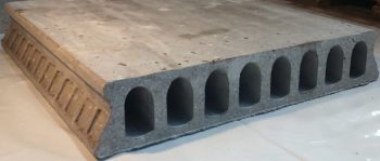
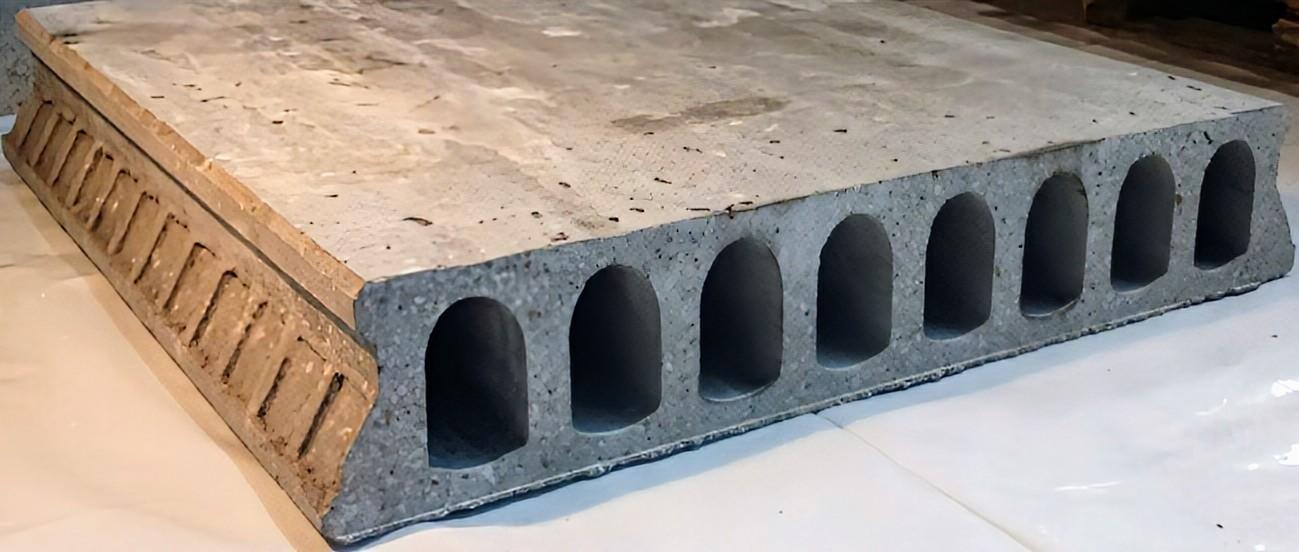
Fig. 1: Shear key on the side of a 200 mm. thick pre-stressed concrete hollow core slabs.
Numerical example:
STEP A: shear resistance generated by the indenting covering 50% of the effective height, 200 mm., on the 250 mm. hollow core slab side, when there is a force of 0,25 N/mm2 normal to the joint.
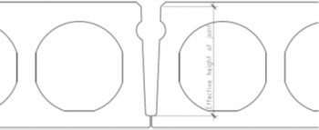
Fig. 2: Out of the total thickness, the shear key is applied to a zone on the sides.
The 50% of the side surface smooth, generates:
vRdi = 0,2 * f ctd + 0,6 * 0,25 N/mm2 = 0,2 * 1,2 + 0,6 * 0,25 = 0,39 N/mm2
The 50% of the side indented surface, generates:
vRdi = 0,5 * 1,2 + 0,9 * 0,25 = 0,825 N/mm2
Total vRdi = 1,21 N/mm2
On a length of 1,0 meter: V= 0,825 * (1000*200/2) + 0,39 * (1000*200/2) = 121,5 kN/m
If smooth, the code limits to 0,15 N/mm2, therefore: V = 0,15 *(1000*200) = 30,0 kN/m
The additional shear force brought by the indenting is: 121,5 – 30,0 = 91,5 kN/m.
STEP B: friction generated by the 40 mm. concrete compression layer on the top of the slabs:
Vc = bw * d * fv = 1.200 mm * 0,04 * 0,63 = 30,24 kN/m (value 0,63N/mm2 following Walraven: ‘Shear under which no shear reinforcement is necessary in elements unreinforced in shear, general limit, for concrete C40 and thicknesses up to 200 mm.)
Therefore, we verify that the additional shear resistance of 91,5 kN/m is bigger to that of the compression layer 30,24 kN/m.
STEP C: If we fit #10 teeth of length 50 mm each and height 100 mm in a slab length of 1,0 meter, according to the example shown, the resistance of each indenting submitted to compression will be the following:
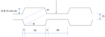
Fig. 3: Eurocode 2 compliant geometry of a shear key as example
Applying IPHA Precast Concrete Structures, II edition, prof. Kim S. Elliott:
tg α = 23 / 57 à α = 22º
X = 8 / cos (α) = 8,63 mm.
The root shear area is: #10 * (3+54+3) * (h=100) = 60.000 mm2
The friction at the indented zone is 0,825 N/mm2, then:
V= 0,825N/mm2 * 60.000 mm2 = 49,50 kN
On each indenting there will be: 49,50 kN / (10 teeth * cos α) = 4,95 / 0,927 = 5,33 kN
The resistance of the teeth taking the weaker concrete (poured at the joint C25/30) including the correction factor is:
fc = 5,33 kN * 1000/100*’X’ = 6,17 N/mm2
fck / ϒc = 25 / 1,5 = 16,66 N/mm2 > 6,17 N/mm2 stress on each tooth. OK.
Tensile forces across the joint must be avoided, meanning σn >= 0. This can be ensured by placing bars of convenient section, As, at the end of the slabs or even better would the hollow core slabs be cast using a plastic concrete, by producing them with a track of exposed wires at both ends.
Conclusion:
In precast concrete construction, the shear key is contemplated by most of the international building codes as a mechanism for the transmission of additional shear.
In affected zones they become an inelastic lateral mechanism for the absorption of energy during a seismic episode.
In non-seismic zones the shear brought by the side indenting equals or even exceeds this from the compression layer on the top of the hollow core slabs of a floor. The same side indenting is also refraining the transmission of vibration at the longitudinal joints for what in most of the cases the use of cross bars or bands of mesh on the top of these joints as it happens to the filigree slabs is no longer required.